Encoders
Encoders are one of the most versatile components on your Yaeltex controller. Each encoder consists of two parts: the rotary element (the turning action) and the switch element (pressing down on the encoder). Both can be configured independently with their own MIDI messages and LED feedback.
Encoder Rotary Configuration
Section titled “Encoder Rotary Configuration”The rotary portion of the encoder sends MIDI messages when you turn the knob. You can configure what type of message it sends, how it responds to rotation speed, and how the LED ring provides visual feedback.
Absolute/Relative Modes (Hardware Mode)
Section titled “Absolute/Relative Modes (Hardware Mode)”The hardware mode determines how encoder rotation values are transmitted. Choose based on your software’s requirements.
| Mode | Value | Description |
|---|---|---|
| Absolute | 0 | MIN to MAX range. Standard mode where the encoder tracks an absolute position between minimum and maximum values. |
| Binary Offset | 1 | (+) 065-127 / (-) 063-000. Increment values are 65-127, decrement values are 63-0. Center point is 64. |
| 2’s Complement | 2 | (+) 001-064 / (-) 127-065. Increment values are 1-64, decrement values are 127-65 (two’s complement encoding). |
| Signed Bit | 3 | (+) 065-127 / (-) 001-063. Uses bit 6 as the sign bit. Positive values have bit 6 set. |
| Signed Bit 2 | 4 | (+) 001-063 / (-) 065-127. Alternative signed bit encoding with opposite sign convention. |
| Single Value | 5 | Increment sends 096, Decrement sends 097. Fixed values for each direction regardless of speed. |
Rotary Speed
Section titled “Rotary Speed”Control how the encoder responds to rotation speed. Faster rotation can either send more increments (acceleration) or maintain a consistent rate (fixed).
| Setting | Description |
|---|---|
| ACCELERATION 1 | Light speed sensitivity - subtle acceleration at higher speeds |
| ACCELERATION 2 | Medium speed sensitivity - moderate acceleration response |
| ACCELERATION 3 | Heavy speed sensitivity - significant value jumps when turning quickly |
| FIXED 1 | Slow fixed rate - consistent small increments regardless of speed |
| FIXED 2 | Medium fixed rate - consistent moderate increments |
| FIXED 3 | Fast fixed rate - consistent large increments |
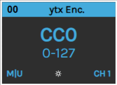
Encoder Rotary Output Message
Section titled “Encoder Rotary Output Message”Configure what MIDI message the encoder sends when rotated.
| Parameter | Description |
|---|---|
| Message Type | The type of MIDI message to send |
| MIDI Channel | Channel 1-16 for the message |
| MIDI Port | NONE, USB, MIDI, or USB+MIDI |
| Parameter | CC number (0-127) or extended parameter (0-16383 for NRPN/RPN) |
| Min Value | Minimum value in the range |
| Max Value | Maximum value in the range |
| Comment | User-defined label for the parameter |
Available Message Types
Section titled “Available Message Types”| Type | Description |
|---|---|
| NOTE | Sends MIDI note messages |
| CC | Control Change - the most common type for encoders |
| VUMETER CC | Special CC for VU meter display in the LED ring |
| PC+ | Program Change increment (increase program number) |
| PC- | Program Change decrement (decrease program number) |
| NRPN | Non-Registered Parameter Number (14-bit, 0-16383 range) |
| RPN | Registered Parameter Number (14-bit, 0-16383 range) |
| PB | Pitch Bend (14-bit resolution) |
| Keystroke | Send keyboard commands instead of MIDI |
Rotary Feedback (LED Ring)
Section titled “Rotary Feedback (LED Ring)”The encoder’s LED ring can display visual feedback based on the current value. Configure how the LEDs respond to incoming MIDI messages.
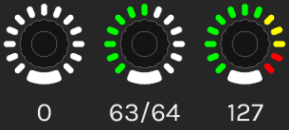
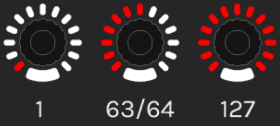
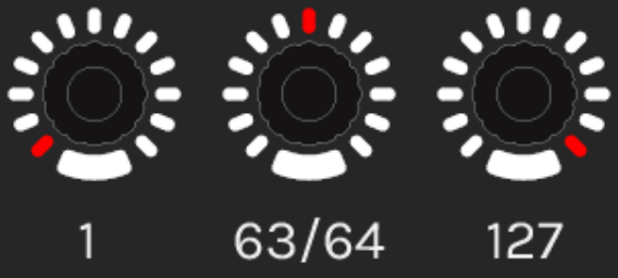
Feedback Display Modes
Section titled “Feedback Display Modes”The LED ring can display values in four different visual styles:
| Mode | Description |
|---|---|
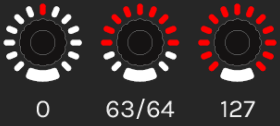
| Fill | LEDs light up from minimum to current value, creating a “filled” arc |
| Spot | A single LED (or small group) indicates the current position |
| Mirror | LEDs fill symmetrically from center outward in both directions |
| Pivot | LEDs extend from center point, going left for values below center, right for values above |
Feedback Source Configuration
Section titled “Feedback Source Configuration”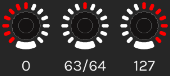
| Parameter | Description |
|---|---|
| Source Port | Where to listen for feedback messages: Local, USB, or MIDI |
| Message Type | The MIDI message type to respond to (typically CC) |
| MIDI Channel | Channel to listen on (1-16) |
| Parameter | CC number or parameter to monitor |
Color Configuration
Section titled “Color Configuration”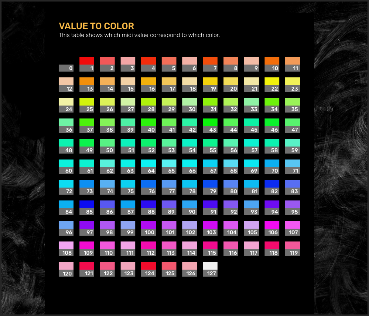
| Mode | Description |
|---|---|
| Fixed Color | LED ring displays a single, constant color |
| Value to Color | LED color changes based on the received MIDI value (requires dedicated MIDI channel) |
Value to Intensity
Section titled “Value to Intensity”Available in firmware v0.20 and later, this feature allows the LED brightness to change based on incoming MIDI values. Configure a dedicated MIDI channel for intensity control in your Controller Options.
Encoder Switch Configuration
Section titled “Encoder Switch Configuration”The encoder switch (pressing down on the knob) can be configured with various behaviors beyond simple button presses.
Switch Modes
Section titled “Switch Modes”| Mode | Abbreviation | Description |
|---|---|---|
| Message | ME | Standard mode - switch sends its configured MIDI message |
| Shift Rotary Action | SRA | While held, the rotary sends an alternate message (secondary CC, different range, etc.) |
| Encoder Fine Adjust | FA | While held, the rotary operates at reduced sensitivity for fine-tuning |
| Double CC | 2CC | Switch toggles between two different CC parameters for the rotary |
| Quick Shift to Bank | QS | Pressing the switch temporarily jumps to another bank |
| Quick Shift + Note | QS+N | Quick shift to bank AND send a note message |
Double Click Behavior
Section titled “Double Click Behavior”Configure what happens when you double-click the encoder switch:
| Option | Description |
|---|---|
| NONE | Double-click has no special function |
| JUMP TO MIN | Double-click sets the rotary value to minimum |
| JUMP TO CENTER | Double-click sets the rotary value to center (64 for 0-127 range) |
| JUMP TO MAX | Double-click sets the rotary value to maximum |
Switch Message Configuration
Section titled “Switch Message Configuration”When using Message (ME) mode, configure the switch’s MIDI output:
| Parameter | Description |
|---|---|
| Momentary/Toggle | Momentary sends note-on while pressed, note-off on release. Toggle alternates between on/off states. |
| MIDI Port | NONE, USB, MIDI, or USB+MIDI |
| Message Type | NOTE, CC, or other MIDI message types |
| Parameter | Note number or CC number (0-127) |
| Min Value | Value sent on release (momentary) or off state (toggle) |
| Max Value | Value sent on press (momentary) or on state (toggle) |
Switch Feedback (LED)
Section titled “Switch Feedback (LED)”The encoder switch typically has its own LED that can provide visual feedback independently of the ring LEDs.
Switch Feedback Configuration
Section titled “Switch Feedback Configuration”| Parameter | Description |
|---|---|
| Source Port | Where to listen for feedback: Local, USB, or MIDI |
| Message Type | MIDI message type to respond to |
| MIDI Channel | Channel to listen on (1-16) |
| Parameter | CC number or note to monitor |
Local Behavior
Section titled “Local Behavior”Control how the switch LED behaves relative to local button presses:
| Option | Description |
|---|---|
| ALWAYS OFF | LED remains off regardless of switch state |
| ON WITH EVENT | LED turns on when switch is pressed/active |
| ALWAYS ON | LED remains on regardless of switch state |
Switch Color Mode
Section titled “Switch Color Mode”| Mode | Description |
|---|---|
| Fixed Color | LED displays a constant color. Choose between LED OFF or LOW INTENSITY for the off state. |
| Value to Color | LED color changes based on received MIDI value |
Configuration Tips
Section titled “Configuration Tips”Setting Up a Basic Encoder
Section titled “Setting Up a Basic Encoder”- Select the encoder card in Kilowhat
- Set Hardware Mode to Absolute (0) for most use cases
- Choose ACCELERATION 2 for balanced speed response
- Set Message Type to CC
- Assign a CC Number (parameter) that matches your DAW or plugin
- Set Min to 0 and Max to 127 for full range
- Configure MIDI Port based on your connection (USB for most setups)
- Set up Feedback to match the output settings so LEDs reflect the current value
Using Shift Rotary Action
Section titled “Using Shift Rotary Action”- Set the switch mode to SRA
- Configure the primary rotary action (e.g., CC 1 for volume)
- Configure the secondary rotary action (e.g., CC 2 for pan)
- Hold the switch and turn to control the secondary parameter
Fine-Tuning with Encoder Fine Adjust
Section titled “Fine-Tuning with Encoder Fine Adjust”- Set the switch mode to FA
- Configure normal rotary sensitivity
- Hold the switch while turning for slower, more precise adjustments
- Ideal for parameters like filter cutoff or pitch fine-tuning
Related
Section titled “Related”- Digital (Buttons) - Configure buttons and switches
- Analog (Faders/Pots) - Configure faders, pots, and joysticks
- Understanding Cards - Learn the card-based interface
- Controller Options - Configure global controller settings