Analog
Analog inputs are continuous controls on your Yaeltex controller, including faders, potentiometers, joystick axes, expression pedals, and other variable-resistance components. Unlike digital inputs (on/off), analog inputs send a continuous range of values as you move them.
Analog Output Configuration
Section titled “Analog Output Configuration”Configure what MIDI messages your analog inputs send as you move them through their range.
Message Type
Section titled “Message Type”Set the type of MIDI message sent when moving the analog control:
| Type | Description |
|---|---|
| NOTE | Sends Note On with velocity determined by the component’s current position |
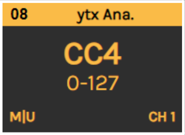
| CC | Control Change message - the most common type for faders and pots |
| Program Change # | Send a specific Program Change number |
| PC+ | Increase Program Change number and send |
| PC- | Decrease Program Change number and send |
| NRPN | Non-Registered Parameter Number (14-bit, 0-16383 range) |
| RPN | Registered Parameter Number (14-bit, 0-16383 range) |
| PB | Pitch Bend message (14-bit resolution) |
| Keystroke | Send a keyboard event instead of MIDI |
MIDI Channel
Section titled “MIDI Channel”Set the MIDI channel (1-16) to send your message.
MIDI Port
Section titled “MIDI Port”Set where the analog message is sent:
| Port | Description |
|---|---|
| USB | Send only via USB connection |
| MIDI | Send only via DIN5 MIDI port |
| USB+MIDI | Send via both ports simultaneously |
Parameter / Key
Section titled “Parameter / Key”Set the parameter to be sent, or the key event if using Keystroke mode.
- For CC/Note/PC: 0-127 (7-bit)
- For NRPN/RPN/PB: 0-16383 (14-bit)
Minimum Value
Section titled “Minimum Value”Set the value sent when the analog control is at its lowest position. The standard MIDI range starts at 0.
Maximum Value
Section titled “Maximum Value”Set the value sent when the analog control is at its highest position:
- 7-bit messages (Note, CC, PC): Maximum is 127
- 14-bit messages (NRPN, RPN, PB): Maximum is 16383
Split Mode
Section titled “Split Mode”Split mode divides an analog component in half, creating two separate controls from one physical component:
- The upper half sends the configured message on the configured channel
- The lower half sends the same message on channel 15 (as set in Controller Options)
How it works:
- First half of travel: Sends on channel 15, value goes from 127 down to 0 toward center
- Second half of travel: Sends on configured channel, value goes from 0 up to 127
Example use case: A single fader controlling both left and right pan, with center position being the neutral point.
Dead Zone
Section titled “Dead Zone”The dead zone feature creates an expanded area around the center position of an analog control. This is useful for:
- Parameters that need a reliable center/neutral position (like EQ, pan, or filter controls)
- Hardware components without a physical center detent
- Preventing accidental value changes when trying to set the middle value
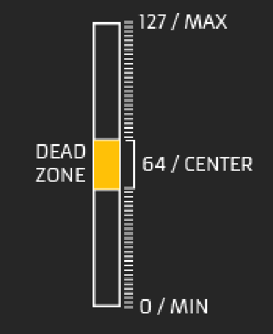
The dead zone expands the physical area that outputs the center value (64 for 0-127 range), making it easier to hit and maintain the neutral position without needing precise physical positioning.
Input Comment
Section titled “Input Comment”Type a descriptive comment for later reference. This appears on the component’s card to help you identify controls in your configuration.
Analog Feedback
Section titled “Analog Feedback”If your analog component has an associated LED or visual indicator, configure how it responds to incoming MIDI messages.
Source Port
Section titled “Source Port”Set which ports the feedback listens to for incoming MIDI messages:
| Port | Description |
|---|---|
| Local | Update feedback locally with component action |
| USB | React to messages received via USB |
| MIDI | React to messages received via DIN5 MIDI port |
| USB+MIDI | React to messages from both ports |
Color Range Enable
Section titled “Color Range Enable”Enable this feature to define different LED colors based on value ranges in the incoming MIDI message.
Example: If receiving NOTE messages, you could set:
- Velocity 1-3: Red
- Velocity 4-8: Blue
- Velocity 9-127: Green
This is particularly useful for visual feedback that changes based on parameter intensity or for Ableton Live clip matrix integration.
Message Type
Section titled “Message Type”Set the MIDI message type the feedback responds to. Usually matches the output configuration:
- Note On/Off
- Control Change
- Program Change
- NRPN
- RPN
- Pitch Bend
MIDI Channel
Section titled “MIDI Channel”Set the MIDI channel (1-16) the feedback responds to. Usually matches the output configuration.
MIDI Parameter
Section titled “MIDI Parameter”Set the MIDI parameter the feedback responds to. Usually matches the output parameter.
| Message Type | Value Range |
|---|---|
| Note / CC / PC | 0-127 |
| NRPN / RPN / PB | 0-16383 |
Color Mode
Section titled “Color Mode”Choose how the LED color behaves:
Fixed Color
Section titled “Fixed Color”Set a specific color for the LED feedback. You can:
- Use the color picker
- Enter a HEX value in
#RRGGBBformat
In Fixed Color mode, you can choose two OFF state options:
| Option | Behavior |
|---|---|
| LED OFF | LED turns completely off when MIN value is received |
| LOW INTENSITY | LED dims to low brightness when MIN value is received, indicating inactive state |
Value to Color
Section titled “Value to Color”The LED color is determined by the received MIDI value, selecting from 128 available colors.
Quick Reference
Section titled “Quick Reference”Output Configuration Summary
Section titled “Output Configuration Summary”| Parameter | Options | Description |
|---|---|---|
| Message Type | NOTE, CC, PC, PC+, PC-, NRPN, RPN, PB, Keystroke | MIDI message type |
| MIDI Channel | 1-16 | Channel for output messages |
| MIDI Port | USB, MIDI, USB+MIDI | Where messages are sent |
| Parameter | 0-127 or 0-16383 | MIDI parameter number |
| Min Value | 0+ | Value at lowest position |
| Max Value | up to 127 or 16383 | Value at highest position |
| Split Mode | On/Off | Divide control into two halves |
| Dead Zone | Value | Center zone size |
Feedback Configuration Summary
Section titled “Feedback Configuration Summary”| Parameter | Options | Description |
|---|---|---|
| Source Port | Local, USB, MIDI | Where feedback listens |
| Color Range | On/Off | Enable value-based color ranges |
| Message Type | Note, CC, PC, NRPN, RPN, PB | Message type to respond to |
| MIDI Channel | 1-16 | Channel to listen on |
| Parameter | 0-127 or 0-16383 | Parameter to respond to |
| Color Mode | Fixed / Value to Color | How LED color is determined |
Configuration Tips
Section titled “Configuration Tips”Setting Up a Basic Fader
Section titled “Setting Up a Basic Fader”- Select the analog card in Kilowhat
- Set Message Type to CC
- Assign a CC Number (parameter) that matches your DAW or plugin
- Set Min to 0 and Max to 127 for full range
- Configure MIDI Port based on your connection (USB for most setups)
- Set MIDI Channel to match your target device
Using Split Mode for Crossfaders
Section titled “Using Split Mode for Crossfaders”- Enable Split Mode for your fader
- The center position becomes the neutral point
- Moving toward one end controls one parameter (on channel 15)
- Moving toward the other end controls another parameter (on configured channel)
- Both halves use the same CC number but different channels
Calibrating with Dead Zone
Section titled “Calibrating with Dead Zone”- Identify controls that need a reliable center position
- Enable Dead Zone and set an appropriate value
- Test by moving the control slowly through center
- Adjust the dead zone size until the center position feels natural
Related
Section titled “Related”- Encoders - Configure rotary encoder components
- Digital (Buttons) - Configure buttons and switches
- Controller Options - Configure takeover mode and other global settings
- Understanding Cards - Learn the card-based interface